1. Electric Open Winch Trolley General Introduction
Kingda electric open winch trolley is a proven component that have been tried and tested on more than 8000 sets crane equipment in the past years. Without need for any additional design or development work, fast, safe and reliable are its features, and without any problems caused by additional interface. This electric open winch trolley are extremely reliable elements for double girder crane (double beam EOT crane or gantry crane).
Kingda Crane not only provides solutions to meet your industry needs, but also supply components that are configured precisely to meet your application requirements. Wear-resistant components and optimum accessibility are more easy for service and maintenance.
2. 1 Benefits of electric open winch trolley
- ► True vertical lift reeving arrangements from 2/2 to 24/2
Compact dimensions
Optimized rope drum
- ► Minimum drum wear thanks to enlarged rope groove opening angle
- ► Long rope service life-also under arduous conditions
- ► Optimum crane approach dimension in combination with high lifting performance: large drum diameters and small crab track gauges ca be achieved thanks to hoist gearbox with a large shaft center distance
- ► Safe operation thanks to an optional second hoist brake
- ► Clear interfaces for ease of assembly and maintenance
- ► Minimum maintenance requirement and easy to service
- ► Short installation times thanks to per-assembled solutions
2. The Advantages of Electric Open Winch Trolley:
- ► Without the need for any additional design or development work: Fast, safe and reliable.
- ► Without any problems caused by additional interface.
- ► Those component are extremely reliable elements for double girder crane, not only hoist trolley, but also open winch trolley.
This Kingda electric open winch trolley applies lightweight design, all lifting load works on trolley’s end carriages, clear trolley force distribution, compact structure layout, high transmission efficiency, low-noise, reduce on whole crane height and self-weight compared with traditional open winch crab.
3. Electric Open winch Trolley Cross Traveling Mechanism
| No. |
component |
Technical features |
Picture demonstration |
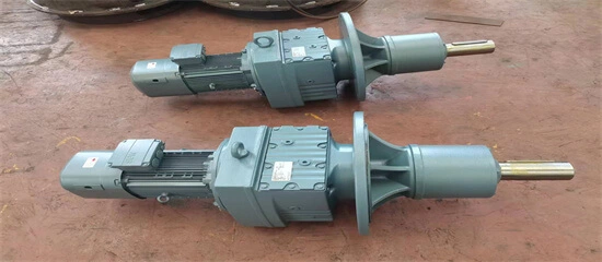
| 1 |
Motor |
3 in 1 compact structure;
Motor insulation class: F,
Protection class:IP55,
Duty-cycle:40%; |
 |
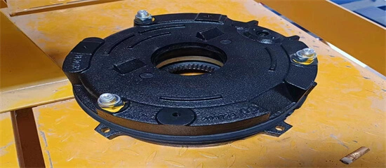
| 2 |
Brake |
Electromagnetic disc braking |
 |
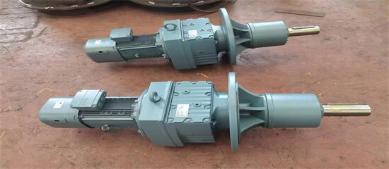
| 3 |
Gear box |
Gear-hardened; Gear grinding or shaving; No need oil change in gearbox’s service life |
 |
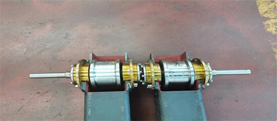
| 4 |
Wheel |
Forging;
Wheel flange and tread hardness:HB330~380 |
 |
| 5 |
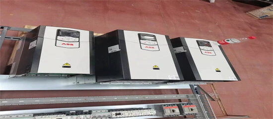
Inverter |
All speed controlled by inverter;
Fast speed in light loading;
Slow speed in heavy loading;
Speed scope: 1:10;
Smooth running and no impact |
 |
| 6 |
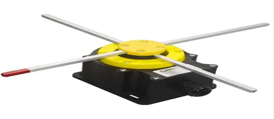
Cross travel limit switch |
Cross hair motion limit switch;
Make crab reducing the speed to 0 before buffer impact on stopper weld on the end of the crab rail |
 |
4. Electric Open Winch Trolley Lifting Mechanism
| No. |
component |
Technical features |
Picture demonstration |
| 1 |
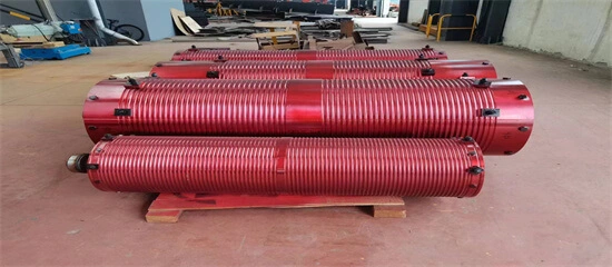
Welding drum |
Short-shaft type steel plate coiled, fitted with bearing support at the two ends;
one of ends is stretched for shaft installation;
simple structure;
easy installation and maintenance; |
 |
| 2 |
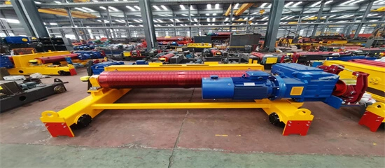
Hoisting motor |
Frequency converter motor;
optimum cooling fan;
Insulation class: F;
Protection level: IP55;
Duty-cycle:40%; |
 |
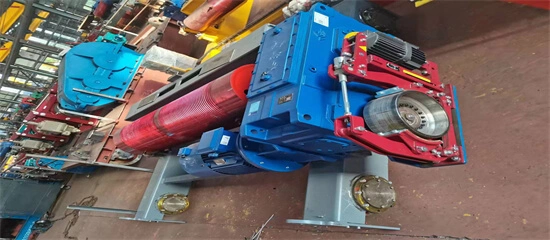
| 3 |
Hoisting gearbox |
Tooth surface carbon case hardening; treatment, Hardness: HRC60;
Gear grinding or shaving;
Light deadweight, good seal, no oil leak; |
 |
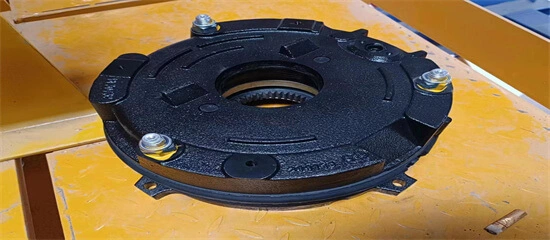
| 4 |
Hoisting brake |
Normally closed type;
With wear automatic compensation;
Can manually release in emergency condition;
Can equipped with double brake(option); |
 |
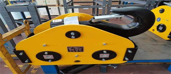
| 5 |
Hook block |
Organized by hook and pulley;
Material: DG34CrMo;
Pulley material: Q245, hot rolling;
Wear-resistance rolling bearing, 360°rotation;
Spring safe lock
All pulleys employ maintenance-free bearing
Reduce wear and tear between rope and pulley; |
 |
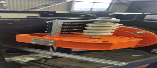
| 6 |
Lifting limit |
Cam rotating type, 4 levels: Up 2 levels, down 2 levels; self-recovery, safe and reliable;
|
 |
| 7 |
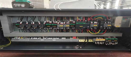
Crab control box |
Protection level: IP55;
Aviation plug
Quick installation |
 |
5. Electric Open Winch Trolley Pictures Demonstrations in Kingda Crane Workshop
6. Electric Open Winch Trolley Inspection and Maintenance
6.1 Safety precaution
- ► 1) Observe the inspection and maintenance site and adjacent areas, set up warning signs and safe working areas;
- ► 2) If encountering adverse weather, such as strong winds, thunderstorms, severe ice and snow, or heavy fog, outdoor inspections and maintenance should be postponed;
- ► 3) The crane should be parked in an undisturbed area;
- ► 4) Disconnect the power supply of the sliding wire or the main circuit breaker of distribution cabinet before conducting maintenance on the crane;
- ► 5) There should be warning signs indicating "inspection in progress" or "maintenance in progress", or the controller switch should be locked in the "off" position, only designated personnel can able to identify and/or lock it;
- ► 6) If there is a load on the electric open winch trolley, the load should be removed;
- ► 7) If the maintenance work poses a danger to the area under crane, warning signs and warning areas should be set up below;
- ► 8) Safe and reliable tools should be used;
- ► 9) Inspection or maintenance personnel should be equipped with personal protective devices (such as protective shoes, safety helmets, seat belts, or protective glasses);
- ► 10) Measures should be taken to prevent electric shock;
- ► 11) During inspection, it is strictly prohibited to close or disconnect the power switch except for instructions given by designated personnel;
- ► 12) When entering a location with a risk of electric shock during inspection, it should be ensured to disconnect the power switch, give a warning sign of "inspection in progress", lock it and/or send personnel to guard it; There should be a warning sign indicating 'under inspection' in the control room;
- ► 13) During the inspection, it is strictly prohibited to operate the electric open winch trolley except for instructions given by designated personnel;
- ► 14) Before the load test, the lifting attachments and the testing load should be checked for defects;
- ► 15) Prohibit other personnel from entering hazardous areas unless authorized;
- ► 16) The inspection should be carried out by two or more inspectors together;
- ► 17) Adequate lighting should be provided during inspection or maintenance;
- ► 18) When welding, appropriate protection should be taken;
- ► 19) After maintenance operations and before the electric open winch trolley resumes normal operation, protective facilities should be reinstalled; Restore safety protection devices and proceed;
- ► 20) Necessary firefighting measures should be taken during maintenance;
- After the maintenance work is completed, the temporary facilities taken during maintenance should be removed and the site cleaned up.
6.2 Daily inspection
Daily inspection items and requirements should be determined based on the specific characteristics of electric open winch trolley, should not be lower than the provisions in Table 7-1.
6.3 Periodical inspection
Based on the working level, working environment, and usage status of electric open winch trolley, determine regular inspection items, inspection requirements, and inspection cycles, which should not be lower than the provisions in Table 6-1.
| No. |
Items |
Methods, Contents, and Requirement |
Recommended Treatments |
Cycle |
| Day |
Week |
Month |
Quarter |
Year |
| 1 |
Technical
Documents |
Attached documents |
Check that the attached drawings, the operation manual and the certificate are complete. |
Correct and improve |
|
|
|
|
○ |
| 2 |
Inspection records |
Check that the past inspection records are complete and there are no untreated defects. |
Correct and improve |
|
|
|
|
○ |
| 3 |
Maintenance records |
Check that the past maintenance records are complete and there is no non-validated maintenance |
Correct and improve |
|
|
|
|
○ |
| 4 |
Other documents |
Check that the past maintenance records are complete and there is no non-validated maintenance. |
Correct and improve |
|
|
|
|
○ |
| 5 |
Mechanism |
Hoisting mechanism |
Check that the hoisting mechanism has no abnormal noise and vibration by a no-load test. |
Maintain |
|
○ |
○ |
○ |
○ |
| 6 |
Trolley travelling mechanism |
Check that the trolley operating mechanism has no abnormal noise and vibration by a no-load test. |
Maintain |
|
○ |
○ |
○ |
○ |
| 7 |
Visually check that there is no deflection, track biting, etc. influencing the trolleys operation. |
Adjust/replace |
|
|
○ |
○ |
○ |
| 8 |
Trolley power supply unit |
Check that the crane power supply unit has no abnormal noise and vibration by a no-load test |
Maintain |
|
|
○ |
○ |
○ |
| 9 |
Key component |
Pulley |
Visually check that the trolley should meet the requirements set forth in Section 4.2.5 ofGB6067.1-2010. |
Repair/change |
|
|
|
○ |
○ |
| 10 |
Visually check that the pulley can turn flexibly. |
Lubricate/adjust |
|
|
|
○ |
○ |
| 11 |
Visually check that the pulley stopper is safe and effective. |
Repair/change |
|
|
|
○ |
○ |
| 12 |
Reel/Drum |
Visually check that the reel should meet the regulations set forth in Section 4.2.4.5 inGB6067.1-2010 |
Change |
|
|
○ |
○ |
○ |
| 13 |
Wire rope |
Check the steel rope according to the methods specified in GB/T5972 and make sure it meet the requirements. |
Change |
|
|
○ |
○ |
○ |
| 14 |
Visually check that the steel rope should have no obvious mechanical damage. |
Repair/change |
|
○ |
○ |
○ |
○ |
| 15 |
Visually check that the steel ropes of the reel and the pulleys have no disengagement from the |
Fasten/adjust |
○ |
○ |
○ |
○ |
○ |
| 16 |
groove. |
Fasten/adjust |
|
|
○ |
○ |
○ |
| 17 |
Brake |
Visually check that the fixation at the end of the steel rope can meet requirements; be sure the press plate is in good operation condition; the end length of the steel rope should be greater than 5 times the diameter. |
Lubricate/adjust |
|
○ |
○ |
○ |
○ |
| 18 |
Visually check that the lubrication of turning points and slewing points meet requirements. |
Maintain |
○ |
○ |
○ |
○ |
○ |
| 19 |
Check through a no-load test that the hoisting mechanism can work properly |
Change |
|
|
○ |
○ |
○ |
| 20 |
Wheel |
Visually check that the brake should meet the requirements set forth in Section 4.2.6.7 of GB6067.1-2010. |
Fasten/adjust/repair/change |
|
|
|
○ |
○ |
| 21 |
Coupling |
Visually check that the wear and deformation of wheel flanges and treads meet the specifications set forth in Section 4.2.7 fGB6067.1-2010 |
Fasten/repair |
|
○ |
○ |
○ |
○ |
| 22 |
Reducer |
Visually check that the coupling has no defects looseness, oil leakage, and abnormal vibration and noise in operation. |
Fasten/repair |
|
|
○ |
○ |
○ |
| 23 |
check that the running reducer has no abnormal noise, vibration, oil leakage and overheat |
oil |
|
|
○ |
○ |
○ |
| 24 |
Bearing |
Visually check that the oil level should be within the required range. |
Change |
|
|
|
○ |
○ |
| 25 |
Trolley rail |
Visually check that the bearing has no abnormal noise and temperature rise. |
Adjust |
|
|
|
|
○ |
| 26 |
joint gap and height difference to make sure they meet relevant standards. |
Change |
|
|
○ |
○ |
○ |
| 27 |
Visually check that the track has no cracks and serious wear-out. |
Fasten/change |
|
|
○ |
○ |
○ |
| 28 |
Safety protection device |
Lifting height limiter |
Visually check that the pneumatic system works normally and has no abnormal noise. |
Fasten/repair |
○ |
○ |
○ |
○ |
○ |
| 29 |
Secondary lifting height limiter |
Check through function testing that the lifting height limiter is fixed securely and functions effectively. |
Fasten/repair |
|
|
○ |
○ |
○ |
| 30 |
anti-crash device |
Visually check that the slewing locking device has no deformation, damage and looseness |
Fasten/repair |
|
|
○ |
○ |
○ |
| 31 |
Buffer and end stopper |
Visually check that the anti-crash device has no deformation and damage and functions effectively |
Fasten/repair/change |
|
|
|
○ |
○ |
| 32 |
Load lifting limiter |
Visually check that the buffer has no deformation and damage and the end stopper has no deformation and open welds. |
Fasten/repair |
|
|
|
|
○ |
| 33 |
Overspeed protection device |
Check through function testing that the load lifting limiter is fixed securely and functions effectively. |
Change |
|
|
|
|
○ |
| 34 |
Emergency stop switch |
Visually check that the control units of the safety monitoring and management system work normally. |
Repair/change |
|
|
|
○ |
○ |
| 35 |
Radiant heat protection device |
Visually check that the clearance between the track sweeper and the track is 5mm~10m |
Fasten/repair |
|
|
|
○ |
○ |
6.4 Inspection and maintenance of main components
6.4.1 Wire rope inspection
Wire rope is a key component for lifting mechanism, which directly affects the safe use of the electric open winch trolley and is often scrapped due to wear and tear. Therefore, it is necessary to regularly inspect and maintain wire rope in accordance with the standard GB/T5972 "Maintenance, Installation, Inspection and Scrapping of Crane Wire Ropes" to ensure the safe and effective operation of the crane.
Regularly carry out the following inspection and maintenance procedures:
Inspect the condition of wire rope in accordance with GB/T5972 "Maintenance, Installation, Inspection, and Scrapping of Crane Steel Wire Ropes". Replace and lubricate the wire rope if necessary.
6.4.1.1 Replacement of wire rope
- ► 1) Replace worn or damaged wire ropes. The model and main performance of the wire rope can be found in the random file:
- ► 2) Lower the hook to the ground to keep the rope loose;
- ► 3) Dismantle the fixed parts of the wire rope (hoist crane);
- ► 4) Remove the rope guide (hoist crane);
- ► 5) Remove the pressure rope plate from the drum;
- ► 6) Put down the old wire rope, coil it neatly and put it into storage;
- ► 7) Take out a new wire rope and keep it lubricated;
- ► 8) Check and ensure that the new wire rope and drum are compatible. Check the certificate of the wire rope to ensure that the model and performance of the wire rope meet the requirements:
- ► 9) There is a pressure plate at the end of the roll for fixing wire rope, the specifications and quantities vary depending on the model. When the hook is in the lowest position, it must be ensured that there are at least two complete coils of wire rope wrapped around the drum at the end of the drum;
- ► 10) Fix the starting end of the wire rope to the drum with a pressure plate, which must be firm and not loose;
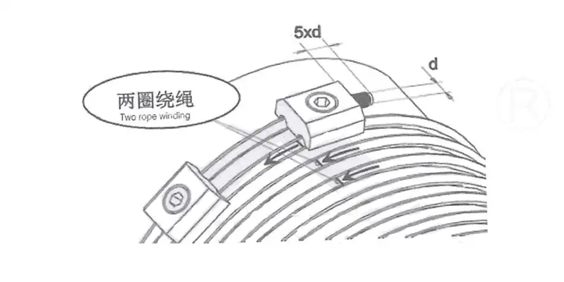
Figure 6-1 schematic diagram of wire rope fixing
- ► 11) Wrap the wire rope onto the drum through lifting motor;
- ► 12) According to the rope winding diagram, correctly thread the wire rope through the pulley;
Figure 6-2 Wire rope winding diagram of hoist trolley crane
Figure 6-3 Wire rope winding diagram of open winch trolley crane
- ► 13) Fix the end of the wire rope on the drum with a pressure plate, which must be firm and free from looseness (open winch trolley crane);
- ► 14) Fix wire rope in the wedge sleeve, tighten wire rope and clamp rope clamp (hoist trolley crane) on the free end of wire rope;
- ► 15) Place the wire rope wedge sleeve on the suspension point, install the pin shaft and lock it firmly (hoist trolley crane);
- ► 16) Clean and install the rope guide (hoist trolley crane);
- ► 17) After replacing the wire rope, adjust and check the lifting limit switch;
- ► 18) Test the condition of wire rope winding. If the wire rope is knotted and causes the hook to rotate, the wire rope must be removed to eliminate the twisting of the wire rope;
| Matters needing attention |
| ► Only wire ropes specified by the crane manufacturer can be installed. |
| ► When uncoiling the wire rope, it should be prevented from tying or twisting. |
| ► When cutting the wire rope, measures should be taken to prevent the rope strands from spreading. |
► Place the wire rope in the wedge sleeve in the correct way, andsuspension hole of the wedge sleeve should be in line with the load-bearing rope.
As shown in the above figure |
6.4.1.2 Installation requirements for wire rope clamps
The minimum number of wire rope clamps required at each connection point is recommended in Table 6-2. When installing the rope clamp, the clamp seat should be fastened to the load-bearing section of the wire rope and the U-shaped bolt should be fastened to the tail end; The distance between two rope clamps is equal to 6~7 times of the diameter of the wire rope; The distance between last rope clamp and the end of the wire rope should not be less than 150mm.
| Table 6-2 Quantity of Steel Rope Clamps |
| Nominal diameter of steel rope/mm |
≤19 |
19~32 |
32~38 |
38~44 |
44~60 |
| Minimum quantity/set of steel rope clamps |
3 |
4 |
5 |
6 |
7 |
6.4.2 Drum inspection
If one of the following situations occurs, the drum should be scrapped:
- ► 1) Surface defects that affect performance (such as cracks);
- ► 2) Wear of the simple wall reaches 20% of the original wall thickness.
6.4.3 Hook inspection
If one of the following situations occurs, the hook should be scrapped:
- ► 1) Surface cracks appear;
- ► 2) Plastic deformation of the dangerous section or neck of the hook;
- ► 3) Torsion deformation of the hook exceeds 10 °;
- ► 4) Dangerous section wear of the hook reaches 5% of the original size;
- ► 5) Deformation of the hook opening reaches 10% of the original size;
- ► 6) Plastic deformation of the hook shank;
- ► 7) Other requirements shall be in accordance with GB10051.3 "Lifting Cranes - Part 3: Inspection of Forged Cranes for Use"
 Defects on the hook shall not be repaired by welding
6.4.4 Pulley inspection
If one of the following situations occurs, the pulley should be scrapped:
- ► 1) Surface defects that affect performance (such as cracks);
- ► 2) Uneven wear of the wheel groove reaches 3mm;
- ► 3) The wear of the groove wall thickness reaches 20% of the original thickness;
4) Due to wear and tear, the diameter at the bottom of the wheel groove has decreased by up to 50% of wire rope’s diameter.
6.4.5 Brake inspection
If one of the following situations occurs to brake parts, the parts should be replaced or the brake should be scrapped
► 1) Driving device
a) Burn out of magnet coil or motor winding;
b) The thruster’s thrust cannot meet the brake release requirement or there is no thrust;
► 2) Brake spring
a) The spring occurs plastic deformation and the deformation reaches more than 10% of the spring’s working deformation;
b) Spring surface occurs more than 20% rust; Or obvious damage such as cracks.
► 3) Transmission component
a) Severe deformation affects performance
b) When severe wear occurs at the main swing point, and the wear leads to a loss of over 20% of the original brake drive stroke;
► 4) Brake pad
a) Riveted or assembled brake pads’ wear amount reaches 50% of the original thickness of the liner;
b) Wear amount and mounted brake pad of steel backer reaches 2/3 of the original thickness of the gasket;
c)Carbonization on the surface of the brake pad; Or the peeling area reaches 30% of the pad area;
d)Cracks or severe cracking on the surface of the brake pad.
► 5) Brake wheel
a) Surface cracks and other defects that affect performance;
b) The brake wheel of the lifting mechanism has a thickness wear of 40% of the original thickness on the brake surface;
c) The brake wheels of other institutions have a thickness wear of 50% of the original thickness on the brake surface;
d) When the unevenness of the wheel surface reaches 1.5mm, if it can be repaired, the thickness of the brake surface after repair should meet the above requirements
6.4.6 Frequency converter inspection
 Due to the influence of temperature, humidity, dust, and vibration in the environment, the internal components of the frequency converter may age, leading to potential faults or reducing the service life of the frequency converter. Therefore, it is necessary to implement daily and regular maintenance and upkeep for frequency converter.
After disconnecting the power supply, as there is still high voltage on the filter capacitor, maintenance or repair of the frequency converter cannot be carried out immediately. It is necessary to wait until the charge light is off and use a multimeter to measure that the bus voltage to not exceed 48V before proceeding.
Vulnerable parts of frequency converter mainly include cooling fan and electrolytic capacitor for filtering, and their service life is closely related to the service environment and maintenance conditions. The general service life is 2-3 years for fans and 4-5 years for electrolytic capacitor. Users can determine the replacement period based on the running time and the specific condition of the parts.
| Daily Inspection Items |
| ► Does the sound of the motor change abnormally during operation |
| ► Is there any vibration generated during motor operation |
| ► Whether the converter fan works normally |
| ► Is the frequency converter overheated |
| ► Effectively remove surface dust on the frequency converter and prevent dust from entering the interior of the frequency converter. |
| ► Especially metal dust. Effectively remove the oil stain of the converter fan. |
6.5 lubrication
To ensure the reliability and lifespan of the crane, it is necessary to regularly lubricate and maintain the crane. If the electric open winch trolley operates in extremely cold conditions (below -20C) and high temperatures (above+55C) for a long time, it is recommended to use synthetic lubricating oil.
Generally, cranes use decentralized lubrication, which involves manually injecting oil into each lubrication point using an oil gun. Centralized lubrication can also be used according to requirements, that is, the grease is pressed into the distributor along the main oil pipe by a manual or electric refueling pump, and the lubrication points of bearings such as the drum, wheel, and fixed pulley are injected with oil along the oil delivery pipe through the distributor.
The design and lubrication of the reducer are carried out in accordance with FEM standards. Under normal conditions, no other maintenance work is required during the safe use cycle. If you need to replace the lubricating oil, please first ensure that the inner casing of the reducer is absolutely clean. Please pay attention to the corresponding lubricating oil grade and filling amount listed in the table below.
| Table 6-3 Brand and filling quantity of lubricating oil |
Electric
open
winch trolley
lifting
mechanism
reducer |
Reducer Mode |
Oil Mode |
Adding Quantity(Litre) |
Every 3 months |
Every 6 months |
Every 3 years |
Every 5 years |
| P3HM5 |
L-CKC220 |
16 |
|
check lubricating oil condition |
replace lubricating oil(if mineral oil) |
replace lubricating oil (if it is synthetic) |
| P3HM6 |
18 |
|
| P3HM7 |
29 |
|
| P4HM9 |
48 |
|
| P4HM10 |
50 |
|
| P4HM12 |
87 |
|
| P4HM13 |
120 |
|
| P4HM15 |
170 |
|
Hoist
trolley
lifting
mechanism
reducer |
GH3201 |
L-CKC680 |
1.4 |
|
| GHX63 |
L-CKC220 |
4 |
|
| GH12500 |
L-CKC680 |
5 |
|
| GH20000 |
L-CKC680 |
9 |
|
| GH25000 |
L-CKC220 |
13 |
|
| GH40000 |
L-CKC220 |
15 |
|
Travelling
reducer |
G…27 |
L-CKC220 |
0.6 |
|
| G…37 |
1 |
|
| G…47 |
1.5 |
|
| G…57 |
2.8 |
|
| G…67 |
2.9 |
|
| G…77 |
6 |
|
| G…87 |
10.8 |
|
| G…97 |
18.5 |
|
| G…107 |
27 |
|
| Wire rope |
No galvanized |
Lubricating grease for wire rope |
Proper amount |
Smear |
|
|
|
| Bearing |
|
Calcium-based grease ZG-3 |
Proper amount |
Smear |
|
|
|
If the electric open winch trolley operates in the following unfavorable environments, the maintenance interval should be shortened:
Highly humid
---Dust, acidic or other corrosive environments
---Environment with large temperature difference
6.6 Recommended tightening torque
| Table 6-4 Bolt Torque Table |
| Specification |
Tightening Torque |
| Strength magnitude 8.8(Nm) |
Strength magnitude 10.9(Nm) |
| M4 |
2.7 |
4 |
| M5 |
5.4 |
7.9 |
| M6 |
9.3 |
14 |
| M8 |
23 |
33 |
| M10 |
45 |
66 |
| M12 |
77 |
115 |
| M14 |
125 |
180 |
| M16 |
190 |
280 |
| M18 |
275 |
390 |
| M20 |
385 |
550 |
| M22 |
530 |
750 |
| M24 |
660 |
950 |
| M30 |
1350 |
1900 |
7. Electric Open Winch Trolley Fault analysis and troubleshooting
When electric open winch trolley has malfunctioned, timely analysis and handling should be carried out. Do not use a crane until the cause of the malfunction has been identified and eliminated.
| Malfunction phenomenon |
Malfunction cause |
Solving method |
| Crane does not move |
No power supply |
Inspect power source and emergency stop button |
| Malfunction of hand-held controller |
Insepct button and wire |
| Excessive brake distance |
Large brake disc clearance |
Adjust clearance |
| Lifting motor does not move, there is noise when press button |
Wiring fault |
Check the main power supply incoming line |
| Contactor issues |
Replace the contactor |
| Brake not open |
Check the brake |
| Lifting motor and long travelling motor only can move in single firection |
Button failure of handheld controller |
Check button |
| Wiring fault |
Check wiring |
| Lifting limiter triggered |
Leave the limiter position |
| Brake does not act |
Brake coil power supply fault |
Check the wiring or repair and replace the worn brake coil |
| Wire rope wear out |
Poor working environment, fixed attachments on the wire rope |
Regularly clean the steel wire rope |
| Abnormal use, resulting in pulley wear |
Restore normal use and replace the pulley |
| Lifting motor moves in wrong direction |
Power phase connection error |
Change the two phase sequences of the power supply voltage and check the direction of operation |
| Active wheels slip |
Oil stains on the rail |
Remove oil stains |
| Excessive braking force |
Adjusting the braking torque |
| Rail gnawing |
Travelling motor out of sync |
Check the motor speed and maintain consistency |
| Inconsistent braking torque during travelling |
Adjusting the braking torque |
| Span deviation |
Check rail span |
 Before handling any faults, power must be cut off;
According to above table, if the fault cannot be determined and eliminated, please contact the manufacturer to use a defective crane;
Using a defective electric open winch trolley can cause serious damage to the equipment or personal injury!